Electromagnetic Control Relays
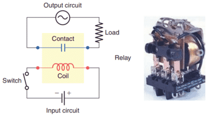
An electrical relay is a magnetic switch. It uses electromagnetism to switch contacts. A relay will usually have only one coil but may have any number of different contacts.
With no current flow through the coil (deenergized), the armature is held away from the core of the coil by spring tension. When the coil is energized, it produces an electromagnetic field. Action of this field, in turn, causes the physical movement of the armature.
Movement of the armature causes the contact points of the relay to open or close. The coil and contacts are insulated from each other; therefore, under normal conditions, no electric circuit will exist between them.
The letter M frequently indicates a motor starter, while CR is used for control relays.
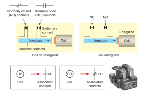
Normally open (NO) contacts are defined as those contacts that are open when no current flows through the coil but that close as soon as the coil conducts a current or is energized.
Normally closed (NC) contacts are closed when the coil is de-energized and open when the coil is energized.
- Each contact is usually drawn as it would appear with the coil de-energized.
- Control relay coils and contacts have separate ratings.
Coils are rated for the type of operating current (DC or AC) and normal operating voltage. Contacts are rated in terms of the maximum amount of current the contacts are capable of handling at a specified voltage level and type (AC or DC).
Control relay contacts generally are not normally designed to carry heavy currents or high voltages.
The contacts are usually rated between 5 and 10 amperes, with the most common rating for the coil voltage being 120 VAC.
Contactors

A contactor is a special type of relay designed to handle heavy power loads that are beyond the capability of control relays.
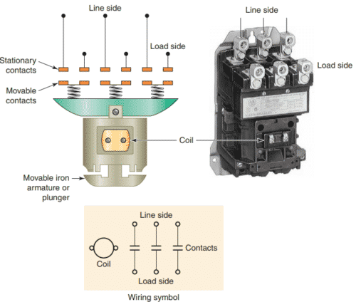
Unlike relays, contactors are designed to make and break higher powered circuits without being damaged.
Such loads include lights, heaters, transformers, capacitors, and electric motors for which overload protection is provided separately or not required.
Programmable controllers normally have an output capacity capable of operating a contactor coil, but not that needed to operate heavy power loads directly.

The image illustrates the application of a PLC used in conjunction with a contactor to switch power on and off to a pump.
The output module is connected in series with the coil to form a low-current switching circuit. The contacts of the contactor are connected in series with the pump motor to form a high-current switching circuit.
Motor Starters

A motor starter is designed to provide power to motors. The motor starter is made up of a contactor with an overload relay attached physically and electrically.
The function of the overload relay can be summarized as follows:
- Overload relays are designed to meet the special protective needs of motor control circuits.
- They allow harmless temporary overloads that occur when a motor starts.
- The overload relay will trip and disconnect power to the motor if an overload condition persists.
- Overload relays can be reset after the overload condition has been corrected.

Figure shows the diagram for a typical three-phase, magnetic motor starter. The operation of the circuit can be summarized as follows:
- When the START button is pressed coil M is energized closing all normally open M contacts.
- The M contacts in series with the motor close to complete the current path to the motor. These contacts are part of the power circuit and must be designed to handle the full load current of the motor.
- Control contact M (across START button) closes to seal in the coil circuit when the START button is released. This contact is part of the control circuit and, as such, is only required to handle the small amount of current needed to energize the coil.
- An overload (OL) relay is provided to protect the motor against current overloads. The normally closed relay contact OL opens automatically when an overload current is sensed to de-energize the M coil and stop the motor.
Motor starters are available in various standard National Electric Manufacturers Association (NEMA) sizes and ratings.
When a PLC needs to control a large motor, it must work in conjunction with a starter as illustrated:

The power requirements for the starter coil must be within the power rating of the output module of the PLC.
Note that the control logic is determined and executed by the program within the PLC and not by the hardwired arrangement of the input control devices.
Good explanation of basic electrical and control systems please email me basic electrical power circuit device and their function as well basic electrical schematics reading guidance
I sent you more basic information by email.
Thanks for commenting!