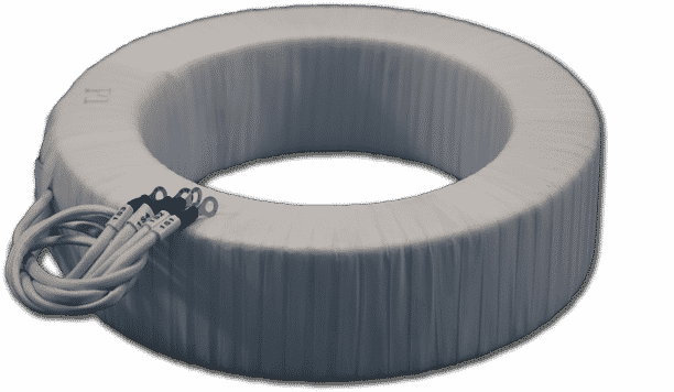
A CT consists of two sets of wire windings around an iron core, you can see how a CT is built in the next video:
Transformers work based on the principle of electromagnetic induction. This principle states that an alternating magnetic flux in the presence of a loop of wire induces a voltage across that loop.
Magnetic flux Φ, is simply the amount of magnetic field passing through a material such as a transformer core.
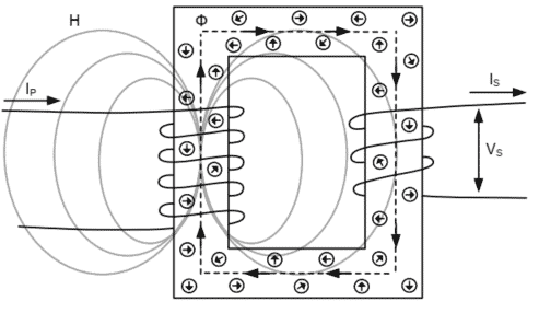
When alternating current Ip flows in the primary winding of a transformer, it generates an alternating magnetic field H,
which corresponds to an alternating magnetic flux Φ, around the transformer core.
This alternating magnetic flux passes through the secondary winding. What happens next depends on the load connected to the secondary winding.
If the secondary is connected to a burden, the alternating magnetic flux in the core induces an alternating voltage Vs
across the secondary winding.
This causes a corresponding alternating current Is to flow in the secondary winding. The alternating current in the secondary creates its own alternating magnetic field and alternating magnetic flux that oppose those created by the primary winding.
These primary and secondary fluxes cancel, leaving a negligible amount of net flux in the core. This occurs until the core becomes saturated.
If the secondary is open-circuited, the alternating magnetic flux in the core induces a very high alternating voltage Vs
across the secondary winding. Vs remains on the terminals with no secondary current flowing, which is why it is very dangerous to open-circuit an in-service CT. Because Is cannot flow, it cannot create an opposing magnetic field, leaving a net flux in the core equal to the flux created by the primary current.
Remember the induction of voltage Vs is a result of the magnetic field created by Ip along with the internal impedances of the transformer and the connected load.
For simplification, we assume a fixed linear burden is connected to the CT. When this is the case, Ohm’s law mandates that the secondary current in the CT and the voltage across the magnetizing impedance are directly proportional.
Why Does a CT Saturate?
In an ideal world, the secondary current leaving the CT Is is an exact replica of the primary current Ip divided by the
ratio of the number of turns in each winding (CT ratio).
However, when a CT saturates, Is does not accurately replicate Ip. The reason a CT saturates is related to what physically occurs inside a CT during the electromagnetic induction process.
The iron core of a CT is made up of a fixed number of magnetic dipoles, which can be thought of as molecular
magnets.
Ideally, these magnets are randomly arranged in polarity throughout the core.
When alternating current Ip flows in the primary winding and generates the magnetic field H, the strength of this magnetic field affects the magnets in the core and causes them to start lining up (in the same direction as the magnetic field) to produce the magnetic flux Φ.
The more current Ip that flows, the stronger the magnetic field H becomes, and the more magnets become lined up.
The number of magnets that are lined up at a given time is the flux density (B).
When all the magnets in the core are aligned in the same direction, the maximum flux density of the core is reached and the CT core is said to be saturated.
The relationship between the magnetic field strength (H) and the magnetic flux density (B) is given by the B-H curve of the
core, as shown:
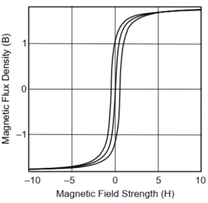
Different types of core materials have different B-H curves, which depend on the ability of the material to support a magnetic field.
How this magnetic behavior affects the ability of the CT to reproduce current is simple: it is the change in flux caused by
the magnets changing direction that induces voltage Vs across the secondary winding of the CT.
Voltage Vs, in turn, generates current Is through the connected circuit. When the core reaches maximum flux density, it is fully saturated and there are no more magnets remaining to change direction. This causes voltage Vs to drop to zero, and current Is ceases to flow.
Remanence in a current transformer (CT)
If a CT has reached saturation and a switch is opened to remove the primary current, we would expect the magnetic field
H to disappear and the flux density B to reduce to zero.
However, flux density does not go to zero when the primary current stops flowing. When the primary current is removed, the magnetic field that causes the magnets to change orientation disappears, and the magnets in the core remain in their present orientation.
The magnets will not move again until exposed to another magnetic field.
The amount of flux density remaining in the core is called remanence.
The fact that the magnets still point in the direction they were in when the magnetic field was removed gives the core “memory” (like a permanent magnet).
This remanence remains in the core until primary current is reapplied. If the reapplied current is opposite in polarity from
the original, flux density is created in the opposite direction of the prior remanence.
The example of a switch being opened to remove primary current is exactly what happens when a relay trips a circuit
breaker during a fault. Recall that when a breaker operates, current is interrupted at a zero crossing.
This remanence remains in the CTs after the breaker opens and affects their behavior the next time they are energized.
Remanence can either help or hinder a CT’s performance, depending on whether the remanence is of the same polarity or opposite polarity of the next current that the CT measures.
It takes more time for the CT to saturate if the remanence is the opposite polarity of the current and less time if it is the same polarity.
Examination of the example B-H curve shows another factor that causes the magnetic core to have remanence.
Note that the curve follows a loop trajectory. The flux density (B) lags the field intensity (H) as it goes through a power system cycle. This phenomenon is called hysteresis.
The only way to remove this remanence is by degaussing the CT.
Degaussing can be done by applying a primary rated current and a variable load to the CT secondary terminals. Start the load at a high resistance to cause the CT to saturate in both the positive and negative directions. Then bring the CT out of saturation by slowly reducing the load (and thus the secondary voltage) to zero.
Sources:
Posts related
Hi there to every one, the contents present at this website are really amazing for people experience, well, keep up the nice work fellows. Mignonne Robinet Calvinna Bernice Clemmy Dola
I like what you guys are up also. Such clever work and reporting! Carry on the excellent works guys I have incorporated you guys to my blogroll. I think it will improve the value of my site . Taryn Barnebas Swope
This is great stuff, its sweet to be in the know.
Your home is valueble for me. Thanks!?This website is mostly a stroll-via for the entire info you wanted about this and didn’t know who to ask. Glimpse here, and you’ll undoubtedly discover it. Free Japan
ive checked this cool site a few times now and i have to say that i find it quite good actually. continue doing what youre doing! 😉
I found this post very helpful which I found on yahoo.Thank you for sharing this information.