The LTC allows voltage regulation and/or phase shifting by varying the transformer ratio under load without interruption, changes the ratio of a transformer by adding turns to or subtracting turns from either the
primary or the secondary winding also the transformer can be equipped with so-called regulating or tap winding for tap changer.
Two switching principles have been used for the load-transfer operation, the high-speed-resistor-type and the reactor-type.
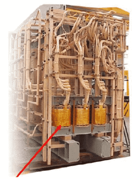
Reactor Oil-Type Load Tap Changers
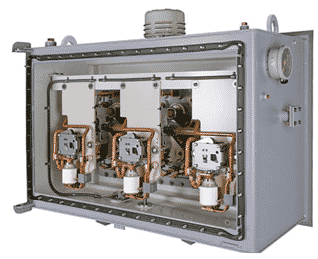
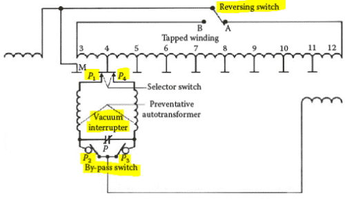
Principal parts of reactor oil type load tap changers
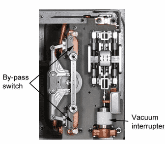
Vacuum Interrupter
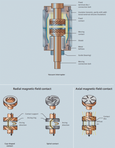
The vacuum switching technology has become the predominant switching technology in the areas of medium-voltage substations and high-capacity power contactors and has replaced oil and SF6 technologies. Today, worldwide more than 60% of the demand for circuit breakers in the medium-power voltage segment is covered by vacuum-type circuit breakers.
- Vacuum interrupter is a hermetically sealed system.
- Arc (drop) voltage in vacuum is considerably lower than in oil or SF6.
- Elimination of the insulating medium as the arc-quenching agent.
- No aging of the quenching medium.
- No interaction/oxidation during switching.
- Extraordinary fast dielectric recovery of up to 10 kV/μs.
By-Pass switch
The designs normally use two auxiliary contacts, the “bypass” switch contacts, to reduce the number of vacuum interrupters required to one interrupter per phase. The tap selector comprises two sets of contacts, which are operated by two separate Geneva wheels.
“Bridging” and “nonbridging” positions
Like any other reactor-type LTC, this tap changer can be operated continuously on “bridging” and “nonbridging” positions.
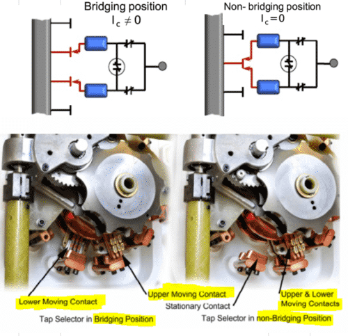
- Bridging positions are those positions where the two tap selector contacts connect to two adjacent taps of the regulating winding.
- On nonbridging positions, both selector contacts connect to the same tap of the regulating winding.
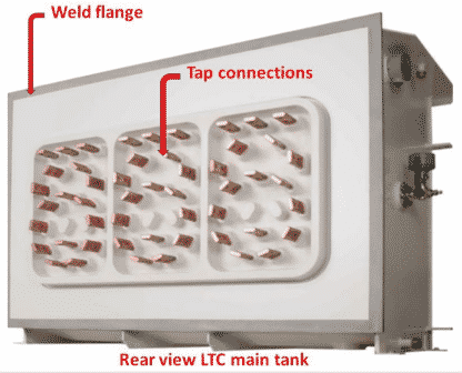
Reactor or preventive autotransformer (PA)
- The PA provides impedance for the tap circuit.
- Prevents shorting the winding when in bridging position.
- Insures very exact split of load current.
- It is mounted inside of the transformer.
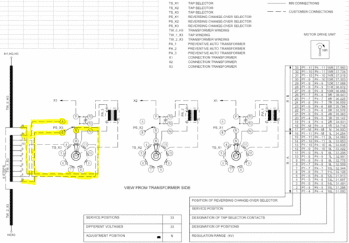
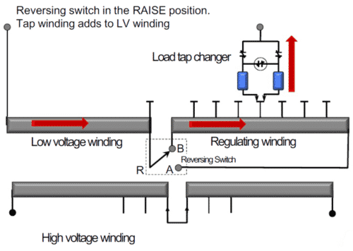
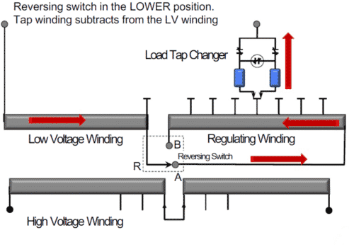
Reversing switch or single reversing change-over selector.
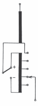
With a reversing change-over selector, the tap winding is added to or subtracted from the main winding so that the regulating range can be doubled or the number of taps reduced.
- Plus configuration (RAISE POSITION)
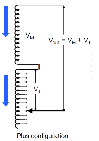
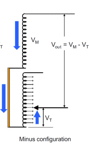
- Minus configuration (LOWER POSITION)
Switching sequence of reactor load tap changer
TAP CHANGE FROM NONBRIDGING POSITION TO BRIDGING POSITION
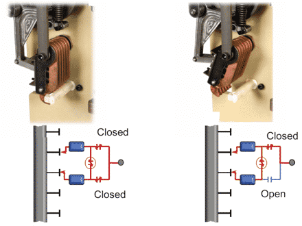
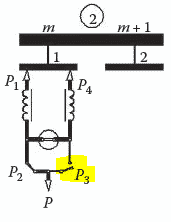
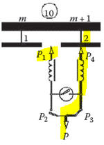
1.-When on a nonbridging position, the LTC selector contacts and bypass contacts are closed, forming two separate current paths, each carrying 50% of the load current.
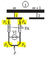
2.-The tap-change operation starts with the opening of contact P3 of the bypass switch. This action routes one-half of the load current through the vacuum interrupter.
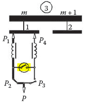
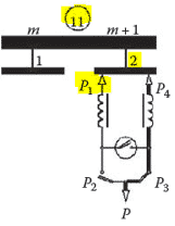
3.-Subsequently, the vacuum interrupter opens, under spring force and extinguishes the arc within the first current zero. This transfers the current flow to the P1–P2 current path.
4.-The tap selector contact P4 can now advance load free to the adjacent tap.
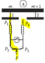
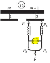
5.-Once it has reached its new operating position.
6.-The vacuum interrupter recloses.
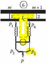
7.-Followed by the reclosing of the bypass switch P3, the LTC is now on a bridging position.
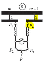
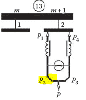
TAP CHANGE FROM BRIDGING POSITION TO NONBRIDGING POSITION
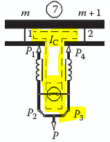
8.-Continuing to the following nonbridging position, the tap-change operation starts now with the opening of the P2 bypass switch contact.
9.-The current now routed through the vacuum interrupter is again extinguished within the first current zero after the opening of the interrupter.
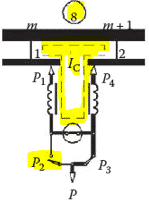
10.-The P1 selector contact can now move load free to the adjacent tap.
11.-Once the tap selector P1 reaches its next operating position.
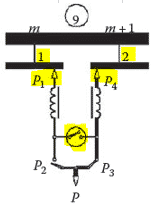
12.-The tap-change operations are completed with the reclosing of the vacuum interrupter.
13.-Then closes the bypass switch contact P2.
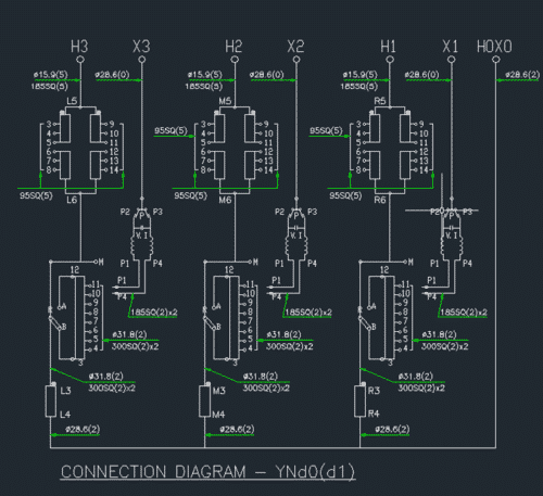
EXAMPLES YNd0(d1)