Memory is the element that stores information, programs, and data in a PLC. The user memory of a PLC includes space for the user program as well as addressable memory locations for storage of data. Data are stored in memory locations by a process called writing. Data are retrieved from memory by what is referred to as reading.
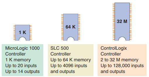
The complexity of the program determines the amount of memory required. Memory elements store individual pieces of information called bits (for binary digits). The amount of memory capacity is specified in increments of 1000 or in “K” increments, where 1 K is 1024 bytes of memory storage (a byte is 8 bits).
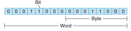
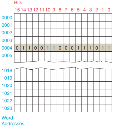
The program is stored in the memory as 1s and 0s, which are typically assembled in the form of 16-bit words.
Memory sizes are commonly expressed in thousands of words that can be stored in the system; thus 2 K is a memory of 2000 words, and 64 K is a memory of 64,000 words. The memory size varies from as small as 1 K for small systems to 32 MB for very large systems.
Memory capacity is an important prerequisite for determining whether a particular processor will
handle the requirements of the specific application.
Memory location refers to an address in the CPU’s memory where a binary word can be stored. A word usually consists of 16 bits. Each binary piece of data is a bit and eight bits make up one byte.
Memory utilization refers to the number of memory locations required to store each type of instruction.
A rule of thumb for memory locations is one location per coil or contact. One K of memory would then allow a program containing 1000 coils and contacts to be stored in memory.
The memory of a PLC may be broken into sections that have specific functions. Sections of memory used to store the status of inputs and outputs are called input status files or tables and output status files or tables.
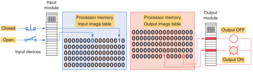
These terms simply refer to a location where the status of an input or output device is stored. Each bit is either a 1 or 0, depending on whether the input is open or closed. A closed contact would have a binary 1 stored in its respective location in the input table, whereas an open contact would have a 0 stored. A lamp that is ON would have a 1 stored in its respective location in the output table, whereas a lamp that is OFF would have a 0 stored.
Input and output image tables are constantly being revised by the CPU. Each time a memory location is examined, the table changes if the contactor coil has changed state. PLCs execute memory-checking routines to be sure that the PLC memory has not been corrupted. This memory checking is undertaken for safety reasons. It helps ensure that the PLC will not execute if memory is corrupted.
Memory Types
Memory can be placed into two general categories: volatile and nonvolatile.
Volatile memory will lose its stored information if all operating power is lost or removed. Volatile memory is easily altered and is quite suitable for most applications when supported by battery backup.
Nonvolatile memory has the ability to retain stored information when power is removed accidentally or intentionally. As the name implies, programmable logic controllers have programmable memory that allows users to develop and modify control programs. This memory is made nonvolatile so that if power is lost, the PLC holds its programming.
Read Only Memory (ROM) stores programs, and data cannot be changed after the memory chip has been manufactured. ROM is normally used to store the programs and data that define the capabilities of the PLC. ROM memory is nonvolatile, meaning that its contents will not be lost if power is lost. ROM is used by the PLC for the operating system. The operating system is burned into ROM by the PLC manufacturer and controls the system software that the user uses to program the PLC.
Random Access Memory (RAM), sometimes referred to as read-write (R/W) memory, is designed so that information can be written into or read from the memory. RAM is used as a temporary storage area of data that may need to be quickly changed. RAM is volatile, meaning that the data stored in RAM will be lost if power is lost. A battery backup is required to avoid losing data in the event of a power loss.
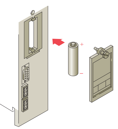
Most PLCs use CMOS-RAM technology for user memory. CMOS-RAM chips have very low current draw and can maintain memory with a lithium battery for an extended time, two to five years in many cases. Some processors have a capacitor that provides at least 30 minutes of battery backup when the battery is disconnected and power is OFF.
Erasable Programmable Read-Only Memory (EPROM) provides some level of security against unauthorized or unwanted changes in a program. EPROMs are designed so that data stored in them can be read, but not easily altered without special equipment. For example, UV EPROMs (ultraviolet erasable programmable readonly memory) can only be erased with an ultraviolet light. EPROM memory is used to back up, store, or transfer PLC programs.
Electrically erasable programmable read-only memory (EEPROM) is a nonvolatile memory that offers the same programming flexibility as does RAM. The EEPROM can be electrically overwritten with new data instead of being erased with ultraviolet light. Because the EEPROM is nonvolatile memory, it does not require battery backup. It provides permanent storage of the program and can be changed easily using standard programming devices. Typically, an EEPROM memory module is used to store, back up, or transfer PLC programs.
Some CPUs support the use of a memory cartridge that provides portable EEPROM storage for the user program. The cartridge can be used to copy a program from one PLC to another similar type PLC.

Flash EEPROMs are similar to EEPROMs in that they can only be used for backup storage. The main difference comes in the flash memory: they are extremely fast at saving and retrieving files. In addition, they do not need to be physically removed from the processor for reprogramming; this can be done using the circuitry within the processor module in which they reside. Flash memory is also sometimes built into the processor module.
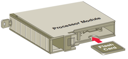
Where it automatically backs up parts of RAM. If power fails while a PLC with flash memory is running, the PLC will resume running without having lost any working data after power is restored.
Number Systems and Codes
Each digit of a binary number is known as a bit. In a PLC the processor-memory element consists of hundreds or thousands of locations. These locations, or registers, are referred to as words. Each word is capable of storing data in the form of binary digits, or bits.
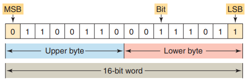
A group of 8 bits is a byte, and a group of 2 or more bytes is a word.
The least significant bit (LSB) is the digit that represents the smallest value, and the most significant bit (MSB) is the digit that represents the largest value.
A bit within the word can exist only in two states: a logical 1 (or ON) condition, or a logical 0 (or OFF) condition. PLC memory is organized using bytes, single words, or double words. Older PLCs use 8-bit or 16-bit memory words while newer systems, such as the ControlLogix platform from Allen-Bradley, use 32-bit double words.
The size of the programmable controller memory relates to the amount of user program that can be stored. If the memory size is 1 K-word, it can store 1024 words or 16,384 (1024 x 16) bits of information using 16 bit words, or 32,768 (1024 x 32) bits using 32-bit words.
All PLCs work internally in the binary system. The processor, being a digital device, understands only 0s and 1s, or binary.
Computer memory is, then, a series of binary 1s and 0s. Figure shows the output status file for an AllenBradley SLC 500 modular chassis, which is made up of single bits grouped into 16-bit words. One 16-bit output file word is reserved for each slot in the chassis.
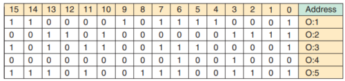
Each bit represents the ON or OFF state of one output point. These points are numbered 0 through 15 across the top row from right to left. The column on the far right lists the output module address. Although the table illustrates sequentially addressed output status file words.
A word is created in the table only if the processor finds an output module residing in a particular slot. If the slot is empty, no word will be created.
Negative Numbers
In binary number systems, such as used in a PLC, it is not possible to use positive and negative symbols to represent the polarity of a number.
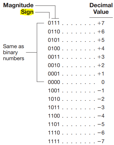
One method of representing a binary number as either a positive or negative value is to use an extra digit, or sign bit, at the MSB side of the number. In the sign bit position, a 0 indicates that the number is positive, and a 1 indicates a negative number.
Another method is by using the complement of a binary number. To complement a binary number, change all the 1s to 0s and all the 0s to 1s. This is known as the 1’s complement form of a binary number.
Example: The 1’s complement of 1001 is 0110.
The most common way to express a negative binary number is to show it as a 2’s complement number.
The 2’s complement is the binary number that results when 1 is added to the 1’s complement.
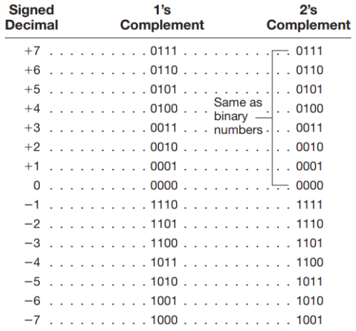
A zero sign bit means a positive number, whereas a 1 sign bit means a negative number. Using the 2’s complement makes it easier for the PLC to perform mathematical operations. The correct sign bit is generated by forming the 2’s complement.
Octal System
The octal numbering system, a base 8 system, is used because 8 data bits make up a byte of information that can be addressed.
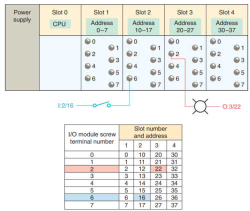
The figure illustrates the addressing of I/O modules using the octal numbering system. The digits range from 0 to 7; therefore, numbers 8 and 9 are not allowed.
Allen-Bradley PLC-5 processors use octal-based I/O addressing while the SLC 500 and Logix controllers use decimal-base 10 addressing.
Octal is a convenient means of handling large binary numbers. One octal digit can be used to express three binary digits. As in all other numbering systems, each digit in an octal number has a weighted decimal value according to its position.
Hexadecimal System
The hexadecimal (hex) numbering system is used in programmable controllers because a word of data consists of 16 data bits, or two 8-bit bytes. The hexadecimal system is a base 16 system, with A to F used to represent decimal numbers 10 to 15.
The hexadecimal numbering system allows the status of a large number of binary bits to be represented in a small space, such as on a computer screen or PLC programming device display.
Binary Coded Decimal (BCD) System
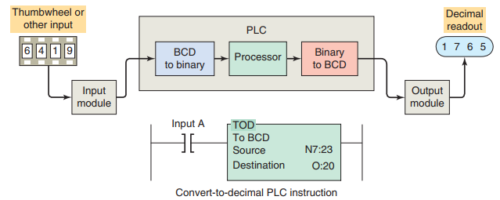
The binary-coded decimal (BCD) system provides a convenient way of handling large numbers that need to be input to or output from a PLC.
The BCD system provides a means of converting a code readily handled by humans (decimal) to a code readily handled by the equipment (binary).
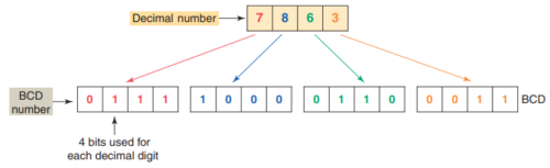
The BCD system uses 4 bits to represent each decimal digit. The 4 bits used are the binary equivalents of the numbers from 0 to 9. In the BCD system, the largest decimal number that can be displayed by any four digits is 9.
The BCD representation of a decimal number is obtained by replacing each decimal digit by its BCD equivalent. To distinguish the BCD numbering system from a binary system, a BCD designation is placed to the right of the units digit.
The BCD representation of the decimal number 7863 is shown:
BCD to-binary conversion is required for the input while binary-to-BCD conversion is required for the output. The PLC convert-to-decimal instruction will convert the binary bit pattern at the source address, N7:23, into a BCD bit pattern of the same decimal value as the destination address, O:20. The instruction executes every time it is scanned, and the instruction is true.
Many PLCs allow you to change the format of the data that the data monitor displays.
The change radix function found on Allen-Bradley controllers allows you to change the display format of data to binary, octal, decimal, hexadecimal, or ASCII.

You can use an binary calculator to convert from one system to other.
Other lenguajes and codes
Depending of the application you will require to use one lenguaje of other:
Gray Code
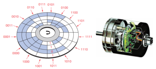
For example, absolute encoders are position transducers that use the Gray code to determine angular position. The Gray code has the advantage that for each “count” (each transition from one number to the next) only one digit changes.
Gray codes are used with position encoders for accurate control of the motion of robots, machine tools, and servomechanisms.
ASCII Code
The keystrokes on the keyboard of a computer are converted directly into ASCII for processing by the computer.
ASCII input modules convert ASCII code input information from an external device to alphanumeric information that the PLC can process. The communication interfacing is done through either an RS-232 or RS-422 protocol. Modules are available that will transmit and receive ASCII files and that can be used to create an operator interface. The user writes a program in the BASIC language that operates in conjunction with the ladder logic as the program runs.
Code used to interface the PLC CPU with alphanumeric keyboards and printers.
Parity Bit
Some PLC communication systems use a binary digit to check the accuracy of data transmission. For example, when data are transferred between PLCs, one of the binary digits may be accidentally changed from a 1 to a 0.
This can happen because of a transient or a noise or because of a failure in some portion of the transmission network.
Parity is a system in which each character transmitted contains one additional bit. That bit is known as a parity bit.
A parity bit is used to detect errors that may occur while a word is moved.
Binary Arithmetic
Arithmetic circuit units form a part of the CPU. Mathematical operations include addition, subtraction, multiplication, and division. Binary addition follows rules similar to decimal addition.