The input/output (I/O) section of a PLC is the section to which all field devices are connected and provides the interface between them and the CPU. Input/output arrangements are built into a fixed PLC while modular types use external I/O modules that plug into the PLC.
Input interface modules accept signals from the machine or process devices and convert them into signals that can be used by the controller.
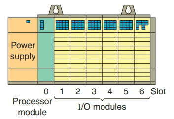
A typical PLC has room for several I/O modules, allowing it to be customized for a particular application by selecting the appropriate modules. Each slot in the rack is capable of accommodating any type of I/O module.
One benefit of a PLC system is the ability to locate the I/O modules near the field devices in order to minimize the amount of wiring required. The processor receives signals from the remote input modules and sends signals back to their output modules via the communication module.
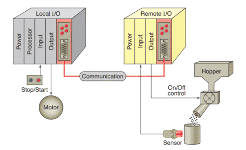
A rack is referred to as a remote rack when it is located away from the processor module. To communicate with the processor, the remote rack uses a special communications network. Each remote rack requires a unique station number to distinguish one from another.
The remote racks are linked to the local rack through a communications module. Cables connect the modules with each other.
If fiber optic cable is used between the CPU and I/O rack, it is possible to operate I/O points from distances greater than 20 miles with no voltage drop.

Coaxial cable will allow remote I/O to be installed at distances greater than two miles. Fiber optic cable will not pick up noise caused by adjacent high power lines or equipment normally found in an industrial environment. Coaxial cable is more susceptible to this type of noise.
The PLC’s memory system stores information about the status of all the inputs and outputs. To keep track of all this information, it uses a system called addressing.
An address is a label or number that indicates where a certain piece of information is located in a PLC’s memory. Just as your home address tells where you live in your city, a device’s or a piece of data’s address tells where information about it resides in the PLC’s memory. That way, if a PLC wants to find out information about a field device, it knows to look in its corresponding address location.
Examples of addressing schemes include rack/slot-based, versions of which are used in Allen-Bradley PLC-5 and SLC 500 controllers, tag-based used in Allen-Bradley ControlLogix controllers, and PC-based control used in soft PLCs.
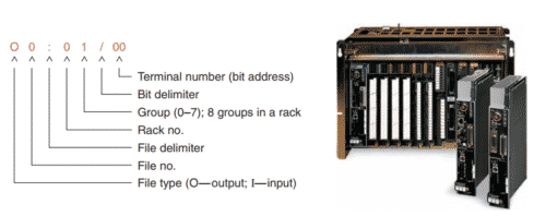
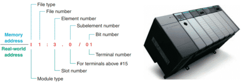
In general, rack/slot-based addressing elements include:
Type—The type determines if an input or output is being addressed.
Slot—The slot number is the physical location of the I/O module. This may be a combination of the rack number and the slot number when using expansion racks.
Word and Bit—The word and bit are used to identify the actual terminal connection in a particular I/O module. A discrete module usually uses only one word, and each connection corresponds to a different bit that makes up the word.
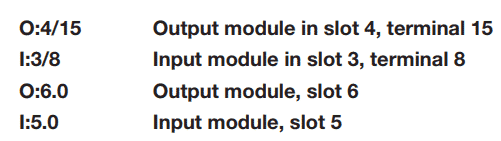
Examples:
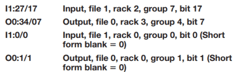
Lights are also added to each module to indicate the ON or OFF status of each I/O circuit. Most output modules
also have blown fuse indicators. The following are typical examples of SLC 500 real-world general input and output
addresses:
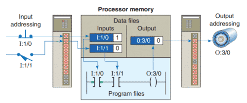
Every input and output device connected to a discrete I/O module is addressed to a specific bit in the PLC’s memory. A bit is a binary digit that can be either 1 or 0.
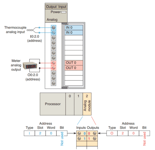
Analog I/O modules use a word addressing format, which allows the entire words to be addressed.
The bit part of the address is usually not used; however, bits of the digital representation of the analog value can be addressed by the programmer if necessary.
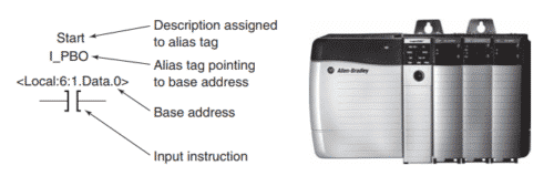
The Allen-Bradley ControlLogix tag-based addressing format. With Logix5000 controllers, you use a tag (alphanumeric name) to address data (variables). Instead of a fixed numeric format, the tag name itself identifies the data. The field devices are assigned tag names that are referenced when the PLC ladder logic program is developed.
Modules
Combination I/O modules can have both input and output connections in the same physical module as illustrated.
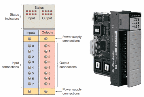
Modules contain terminals for each input and output connection, status lights for each of the inputs and outputs, and connections to the power supply used to power the inputs and outputs. Terminal and status light arrangements vary with different manufacturers.
Most PLC modules have plug-in wiring terminal strips. The terminal block is plugged into the actual module as illustrated:
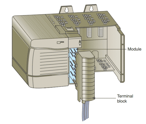
Unless otherwise specified, never install or remove I/O modules or terminal blocks while the PLC is powered.
A module inserted into the wrong slot could be damaged by improper voltages connected through the wiring
arm.
The standard I/O module has eight inputs or outputs. A high-density module may have up to 64 inputs or outputs. The advantage of the high-density module is that it is possible to install up to 64 inputs or outputs in one slot for greater space savings. The only disadvantage is that the high-density output modules cannot handle as much current per output.