Discrete devices are inputs and outputs that have only two states: on and off. In comparison, analog devices represent physical quantities that can have an infinite number of values. Typical analog inputs and outputs vary from 0 to 20 milliamps, 4 to 20 milliamps, or 0 to 10 volts.
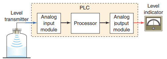
The figure illustrates how PLC analog input and output modules are used in measuring and displaying the level of fluid in a tank. The analog input interface module contains the circuitry necessary to accept an analog voltage or current signal from the level transmitter field device. This input is converted from an analog to a digital value for use by the processor. The circuitry of the analog output module accepts the digital value from the processor and converts it back to an analog signal that drives the field tank level meter.
Analog input modules normally have multiple input channels that allow 4, 8, or 16 devices to be interface to the PLC. The two basic types of analog input modules are voltage sensing and current sensing. Analog sensors measure a varying physical quantity over a specific range and generate a corresponding voltage or current signal. Common physical quantities measured by a PLC analog module include temperature, speed, level, flow, weight, pressure, and position. For example, a sensor may measure temperature over a range of 0 to 500°C, and output a corresponding voltage signal that varies between 0 and 50 mV.
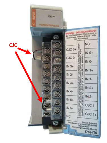
The figure illustrates an example of a voltage sensing input analog module used to measure temperature. The connection diagram applies to an Allen-Bradley MicroLogic 4-channel analog thermocouple input module.

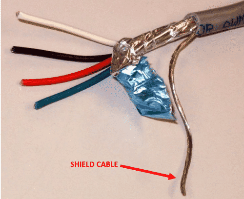
A varying DC voltage in the low millivolt range, proportional to the temperature being monitored, is produced by the thermocouple. This voltage is amplified and digitized by the analog input module and then sent to the processor on command from a program instruction. Because of the low voltage level of the input signal, a twisted shielded pair cable is used in wiring the circuit to reduce unwanted electrical noise signals that can be induced in the conductors from other wiring.
When using an ungrounded thermocouple, the shield must be connected to ground at the module end. To obtain accurate readings from each of the channels, the temperature between the thermocouple wire and the input channel must be compensated for a cold junction compensating (CJC), thermistor is integrated in the terminal block for this purpose.
The transition of an analog signal to digital values is accomplished by an analog-to-digital (A/D) converter, the main element of the analog input module.
Analog voltage input modules are available in two types: unipolar and bipolar.
Unipolar modules can accept an input signal that varies in the positive direction only. For example, if the field device outputs 0 V to +10 V, then the unipolar modules would be used.
Bipolar signals swing between a maximum negative value and a maximum positive value. For example, if the field device outputs -10 V to +10 V a bipolar module would be used.
The resolution of an analog input channel refers to the smallest change in input signal value that can be sensed and is based on the number of bits used in the digital representation.
Analog input modules must produce a range of digital values between a maximum and minimum value to represent the analog signal over its entire span.
Typical specifications are as follows:

When connecting voltage sensing inputs is important to minimize signal degrading and the effects of electromagnetic noise interference induced along the connecting conductors.
Current input signals, which are not as sensitive to noise as voltage signals, are typically not distance limited. Current sensing input modules typically accept analog data over the range of 4 mA to 20 mA, but can accommodate signal ranges of –20 mA to +20 mA.
The loop power may be supplied by the sensor or may be provided by the analog output module as illustrated.
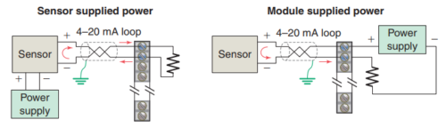
Shielded twisted pair cable is normally recommended for connecting any type analog input signal.
Example:
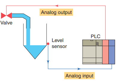
The figure illustrates the use of analog I/O modules in a typical PLC control system. In this application, the PLC
controls the amount of fluid placed in a holding tank by adjusting the percentage of the valve opening. The analog output from the PLC is used to control the flow by controlling the amount of the valve opening. The valve is initially open 100 percent. As the fluid level in the tank approaches the preset point, the processor modifies the output, which adjusts the valve to maintain a set point.
Typical Analog I/O Module Specifications
CHANNELS PER MODULE
Whereas individual circuits on discrete I/O modules are referred to as points, circuits on analog I/O modules are often referred to as channels. These modules normally have 4, 8, or 16 channels. Analog modules may allow for either
single-ended or differential connections. Single-ended connections use a single ground terminal for all channels or for groups of channels. Differential connections use a separate positive and negative terminal for each channel.
If the module normally allows 16 single-ended connections, it will generally allow only 8 differential connections. Single-ended connections are more susceptible to electrical noise.
INPUT CURRENT/VOLTAGE RANGE(S)
These are the voltage or current signal ranges that an analog input module is designed to accept. The input ranges
must be matched accordingly to the varying current or voltage signals generated by the analog sensors.
OUTPUT CURRENT/VOLTAGE RANGE(S)
This specification defines the current or voltage signal ranges that a particular analog output module is designed to output under program control. The output ranges must be matched according to the varying voltage or current signals that will be required to drive the analog output devices.
INPUT PROTECTION
Analog input circuits are usually protected against accidentally connecting a voltage that exceeds the specified
input voltage range.
RESOLUTION
The resolution of an analog I/O module specifies how accurately an analog value can be represented digitally. This specification determines the smallest measurable unit of current or voltage. The higher the resolution (typically specified in bits), the more accurately an analog value can be represented.
INPUT IMPEDANCE AND CAPACITANCE
For analog I/Os, these values must be matched to the external device connected to the module. Typical ratings are in Megohm (MΩ) and picofarads (pF).
COMMON-MODE REJECTION
Noise is generally caused by electromagnetic interference, radio frequency interference, and ground loops.
Common-mode noise rejection applies only to differential inputs and refers to an analog module’s ability to prevent noise from interfering with data integrity on a single channel and from channel to channel on the module. Noise that is picked up equally in parallel wires is rejected because the difference is zero. Twisted pair wires are used to ensure that this type of noise is equal on both wires. Common-mode rejection is normally expressed in decibels or as a ratio.