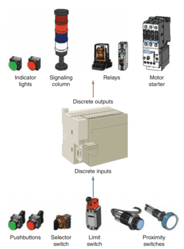
The most common type of I/O interface module is the discrete type. This type of interface connects field input devices of the ON/OFF nature such as selector switches, pushbuttons, and limit switches. Likewise, output control is limited to devices such as lights, relays, solenoids, and motor starters that require simple ON/OFF switching.
Discrete input modules perform four tasks in the PLC control system:
- Sense when a signal is received from a field device.
- Convert the input signal to the correct voltage level for the particular PLC.
- Isolate the PLC from fluctuations in the input signal’s voltage or current.
- Send a signal to the processor indicating which sensor originated the signal.
A simplified diagram for a single output of a discrete AC output module is shown:
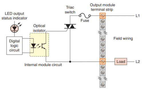
Individual AC outputs are usually limited by the size of the triac to 1 A or 2 A. The maximum current load for any one module is also specified.
To protect the output module circuits, specified current ratings should not be exceeded.
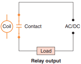
For controlling larger loads, such as large motors, a standard control relay is connected to the output module. The contacts of the relay can then be used to control a larger load or motor starter, as shown:

When a control relay is used in this manner, it is called an interposing relay. Output modules can be purchased with transistor, triac, or relay output.
Triac outputs can be used only for control of AC devices.

Transistor outputs can be used only for control of DC device.

The discrete relay contact output module uses electromechanical as the switching element. These relay outputs can be used with AC or DC devices, but they have a much slower switching time compared to solidstate outputs.
Allen-Bradley modules are color-coded for identification as follows:

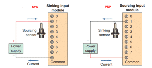
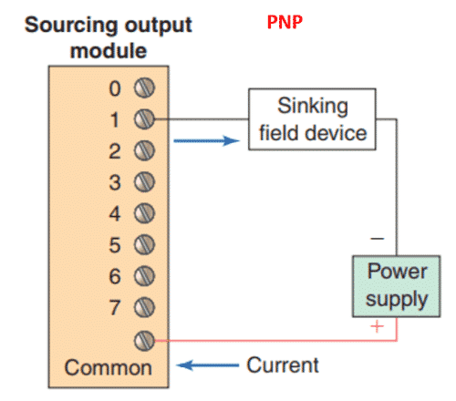
The internal circuitry of some field devices requires that they be used in sinking or sourcing circuits. In general, sinking (NPN) and sourcing (PNP) are terms used to describe a current signal flow relationship between field input and output devices in a control system and their power supply.
The figure illustrates the current flow relationship between sinking and sourcing inputs to a DC input module:
The figure illustrates the current flow relationship between sinking and sourcing outputs to a DC output module. DC input and output circuits are commonly connected with field devices that have some form of internal solid-state circuitry that needs a DC signal voltage to function.
Field devices connected to the positive (+) side of the field power supply are classified as sourcing field devices.
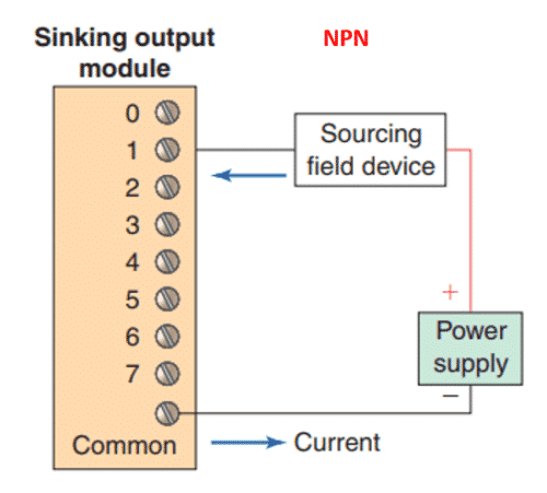
Conversely, field devices connected to the negative (-) side or DC common of the field power supply are sinking field devices.
Typical Discrete I/O Module Specifications
NOMINAL INPUT VOLTAGE
This discrete input module voltage value specifies the magnitude (e.g., 5 V, 24 V, 230 V) and type (AC or DC) of user-supplied voltage that a module is designed to accept.
Input modules are typically designed to operate correctly without damage within a range of plus or minus 10 percent of the input voltage rating. With DC input modules, the input voltage may also be expressed as an operating range (e.g., 24–60 volts DC) over which the module will operate.
INPUT THRESHOLD VOLTAGES
This discrete input module specification specifies two values: a minimum ON-state voltage that is the minimum voltage at which logic 1 is recognized as absolutely ON; and a maximum OFF-state voltage which is the voltage at which logic 0 is recognized as absolutely OFF.
NOMINAL CURRENT PER INPUT
This value specifies the minimum input current that the discrete input devices must be capable of driving to operate the input circuit. This input current value, in conjunction with the input voltage, functions as a threshold to protect against detecting noise or leakage currents as valid signals.
AMBIENT TEMPERATURE RATING
This value specifies the maximum temperature of the air surrounding the I/O modules should be for best-operating conditions.
INPUT ON/OFF DELAY
Also known as response time, this value specifies the maximum time duration required by an input module’s circuitry to recognize that a field device has switched ON (input ON-delay) or switched OFF (input OFF- delay).
This delay is a result of filtering circuitry provided to protect against contact bounce and voltage transients. This input delay is typically in the 9 to 25-millisecond range.
OUTPUT VOLTAGE
This AC or DC value specifies the magnitude (e.g., 5 V, 115 V, 230 V) and type (AC or DC) of user-supplied voltage at which a discrete output module is designed to operate.
The output field device that the module interfaces to the PLC must be matched to this specification. Output modules are typically designed to operate within a range of plus or minus 10 percent of the nominal output voltage rating.
OUTPUT CURRENT
These values specify the maximum current that a single output and the module as a whole can safely carry under
load (at rated voltage). This rating is a function of the module’s components and heat dissipation characteristics. A device drawing more than the rated output current results in overloading, causing the output fuse to blow. As an example, the specification may give each output a current limit of 1 Amp. The overall rating of the module current will normally be less than the total of the individuals. The overall rating might be 6 Amps because each of the eight devices would not normally draw their 1 Amps at the same time. Other names for the output current rating are maximum continuous current and maximum load current.
INRUSH CURRENT
An inrush current is a momentary surge of current that an AC or DC output circuit encounters when energizing inductive, capacitive, or filament loads. This value specifies the maximum inrush current and duration (e.g., 20 A for 0.1 s) for which an output circuit can exceed its maximum continuous current rating.
SHORT CIRCUIT PROTECTION
Short circuit protection is provided for AC and DC output modules by either fuses or some other current-limiting circuitry. This specification will designate whether the particular module’s design has individual protection for each circuit or if fuse protection is provided for groups (e.g., 4 or 8) of outputs.
LEAKAGE CURRENT
This value specifies the amount of current still conducting through an output circuit even after the output has been
turned off. Leakage current is a characteristic exhibited by solid-state switching devices such as transistors and triacs and is normally less than 5 milliamperes. Leakage current is normally not large enough to falsely trigger an output device but must be taken into consideration when switching very low current sensitive devices.
ELECTRICAL ISOLATION
Recall that I/O module circuitry is electrically isolated to protect the low-level internal circuitry of the PLC from high voltages that can be encountered from field device connections. The specification for electrical isolation, typically 1500 or 2500 volts AC, rates the module’s capacity for sustaining an excessive voltage at its input or output terminals. Although this isolation protects the logic side of the module from excessive input or output voltages or current, the power circuitry of the module may be damaged.
POINTS PER MODULE
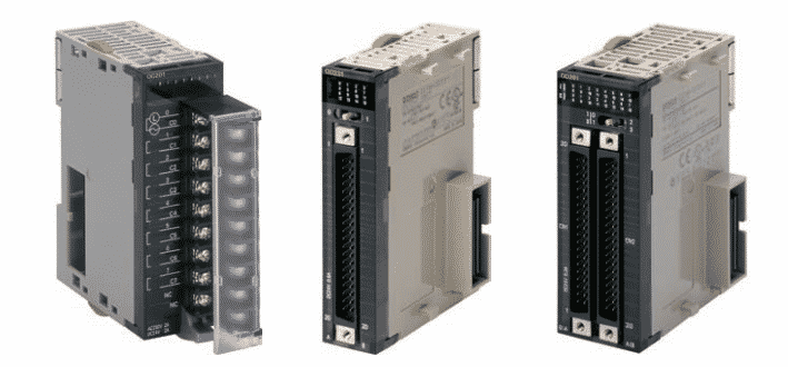
This specification defines the number of field inputs or outputs that can be connected to a single module. Most commonly, a discrete module will have 8, 16, or 32 circuits; however, low-end controllers may have only 2 or 4 circuits. Modules with 32 or 64 input or output bits are referred to as high-density modules. Some modules provide more than one common terminal, which allows the user to use different voltage ranges on the same card as well as to distribute the current more effectively.
BACKPLANE CURRENT DRAW
This value indicates the amount of current the module requires from the backplane. The sum of the backplane current drawn for all modules in a chassis is used to select the appropriate chassis power supply rating.