Electrical “lockout” is the process of removing the source of electrical power and installing a lock, which prevents the power from being turned ON. Electrical “tagout” is the process of placing a danger tag on the source of electrical power, which indicates that the equipment may not be operated until the danger tag is removed.
This procedure is necessary for the safety of personnel in that it ensures that no one will inadvertently energize the equipment while it is being worked on. Electrical lockout and tagout is used servicing electrical equipment that does not require power to be on to perform the service as in the case of motor alignment or replacement of a motor or motor control component.
The following are the basic steps in a lockout procedure:
• Prepare for machinery shutdown: Document all lockout procedures in a plant safety manual.
This manual should be available to all employees and outside contractors working on the premises.
Management should have policies and procedures for safe lockout and should also educate and train
everyone involved in locking out electrical or mechanical equipment. Identify the location of all
switches, power sources, controls, interlocks, and other devices that need to be locked out in order to
isolate the system.
• Machinery or equipment shutdown: Stop all running equipment by using the controls at or near the
machine.
• Machinery or equipment isolation: Disconnect the switch (do not operate if the switch is still under load). Stand clear of the box and face away while operating the switch with the left hand (if the switch is on the right side of the box).
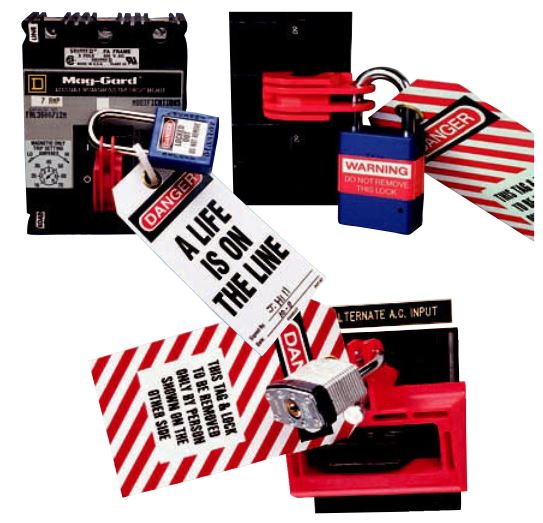
• Lockout and tagout application: Lock the disconnect switch in the OFF position. If the switch box is the breaker type, make sure the locking bar goes right through the switch itself and not just the box cover. Some switch boxes contain fuses, and these should be removed as part of the lockout process. If this is the case, use a fuse puller to remove them.
Use a tamper-proof lock with one key, which is kept by the individual who owns the lock. Combination locks, locks with master keys, and locks with duplicate keys are not recommended.
Tag the lock with the signature of the individual performing the repair and the date and time of the
repair. There may be several locks and tags on the disconnect switch if more than one person is working on the machinery. The machine operator’s (and/ or the maintenance operator’s) lock and tag will be present as well as the supervisor’s.
Release of stored energy: All sources of energy that have the potential to unexpectedly start up, energize, or release must be identified and locked, blocked, or released.
• Verification of isolation: Use a voltage test to determine that voltage is present at the line side of the switch or breaker. When all phases of outlet are dead with the line side live, you can verify the isolation. Ensure that your voltmeter is working properly by performing the “live-dead-live” check before each use: First check your voltmeter on a known live voltage source of the same voltage range as the circuit you will be working on. Next check for the presence of voltage on the equipment you have locked out. Finally, to ensure that your voltmeter did not malfunction, check it again on the known live source.

• Lockout/tagout removal: Remove tags and locks when the work is completed. Each individual must remove his or her own lock and tag. If there is more than one lock present, the person in charge of the work is the last to remove his or her lock. Before reconnecting the power, check that all guards are in place and that all tools, blocks, and braces used in the repair are removed. Make sure that all employees stand clear of the machinery.
Sources: Electric Motors and Control Systems-Frank D. Petruzella
Complementary video