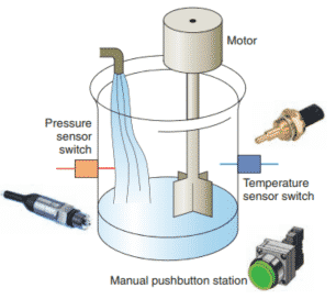
Consider the simple process control problem illustrated.
Here a mixer motor is to be used to automatically stir the liquid in a vat when the temperature and pressure reach preset values.
In addition, direct manual operation of the motor is provided by means of a separate pushbutton station.
The process is monitored with temperature and pressure sensor switches that close their respective contacts when conditions reach their preset values.
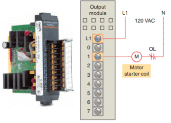
This device would be hardwired to an appropriate output module according to the PLC manufacturer’s addressing location scheme.
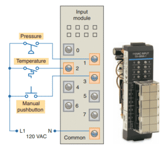
Typical wiring connections for a 120 VAC modular configured input module is shown.
Typical wiring connections for a 120 VAC modular configured output module is shown.
Next, the PLC ladder logic program would be constructed and entered into the memory of the CPU.
A typical ladder logic program for this process is shown.
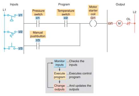
Each input and output device is given an address, which lets the PLC know where it is physically connected. Note that the I/O address format will differ, depending on the PLC model and manufacturer.
Instructions are stored in the user program portion of the processor memory. During the program scan the controller monitors the inputs, executes the control program, and changes the output accordingly.
For the program to operate, the controller is placed in the RUN mode, or operating cycle. During each operating cycle, the controller examines the status of input devices, executes the user program, and changes outputs accordingly.
Each symbol can be thought of as a set of normally open contacts.
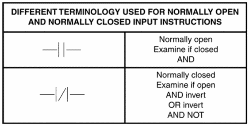
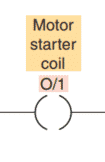
The next symbol is considered to represent a coil that, when energized, will close a set of contacts.
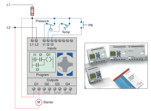
In the ladder logic program, the coil O/1 is energized when contacts I/1 and I/2 are closed or when contact I/3 is closed.
The RUN operation for the process control scheme can be described by the following sequence of events:
- First, the pressure switch, temperature switch, and pushbutton inputs are examined and their status is recorded in the controller’s memory.
- A closed contact is recorded in memory as logic 1 and an open contact as logic 0.
- Next the ladder diagram is evaluated, with each internal contact given an OPEN or CLOSED status according to its recorded 1 or 0 state.
- When the states of the input contacts provide logic continuity from left to right across the rung, the output coil memory location is given a logic 1 value and the output module interface contacts will close.
- When there is no logic continuity of the program rung, the output coil memory location is set to logic 0 and the output module interface contacts will be open.
- The completion of one cycle of this sequence by the controller is called a scan. The scan time, the time required for one full cycle, provides a measure of the speed of response of the PLC.
- Generally, the output memory location is updated during the scan but the actual output is not updated until the end of the program scan during the I/O scan.
The next figure shows a typical wiring required to implement the process control scheme using a fixed PLC Allen-Bradley Pico controller equipped with 8 inputs and 4 outputs is used to control and monitor the process.