A typical PLC can be divided into parts, these are the central processing unit (CPU), the input/output (I/O) section, the power supply, and the programming device.
Input/output (I/O) section
The I/O system forms the interface by which field devices are connected to the controller. The purpose of this interface is to condition the various signals received from or sent to external field devices. Input devices such as pushbuttons, limit switches, and sensors are hardwired to the input terminals. Output devices such as small motors, motor starters, solenoid valves, and indicator lights are hardwired to the output terminals.
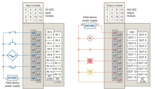
The external devices are also referred to as “field” or “real-world” inputs and outputs. The terms field or real world are used to distinguish actual external devices that exist and must be physically wired from the internal user program that duplicates the function of relays, timers, and counters.
There are two ways in which I/Os (Inputs/Outputs) are incorporated into the PLC: fixed and modular.
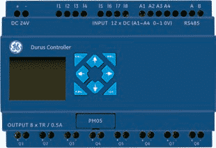
Fixed I/O is typical of small PLCs that come in one package with no separate, removable units.
The processor and I/O are packaged together, and the I/O terminals will have a fixed number of connections built in for inputs and outputs. The main advantage of this type of packaging is lower cost.
The number of available I/O points varies and usually can be expanded by buying additional units of fixed I/O. One disadvantage of fixed I/O is its lack of flexibility; you are limited in what you can get in the quantities and types dictated by the packaging. Also, for some models, if any part in the unit fails, the whole unit has to be replaced.
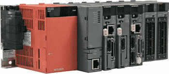
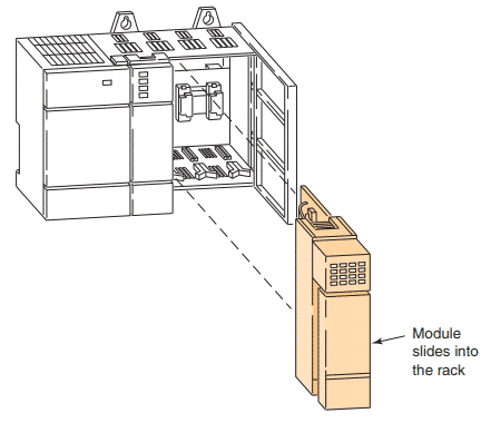
Modular I/O is divided by compartments into which separate modules can be plugged. This feature greatly increases your options and the unit’s flexibility. You can choose from the modules available from the manufacturer and mix them any way you desire.
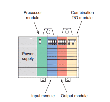
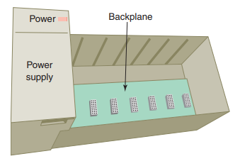
The basic modular controller consists of a rack, power supply, processor module (CPU), input/output (I/O modules), and an operator interface for programming and monitoring. The modules plug into a rack. When a module is slid into the rack, it makes an electrical connection with a series of contacts called the backplane, located at the rear of the rack.
The power supply
The power supply supplies DC power to other modules that plug into the rack. For large PLC systems, this power supply does not normally supply power to the field devices. With larger systems, the power to field devices is provided by external alternating current (AC) or direct current (DC) supplies. For some small micro PLC systems, the power supply may be used to power field devices.
The PLC power supply provides the necessary power (typically 5 VDC) to the processor and I/O modules plugged into the backplane of the rack.
Power supplies are available for most voltage sources encountered. The power supply converts 115 VAC or 230 VAC into the usable DC voltage required by the CPU, memory, and I/O electronic circuitry. PLC power supplies are normally designed to withstand momentary losses of power without affecting the operation of the PLC. Holdup time, which is the length of time a PLC can tolerate a power loss, typically ranges from 10 milliseconds to 3 seconds.
The central processing unit (CPU)
The PLC processor is also connected to the backplane and can communicate with all the modules in the rack.
The processor (CPU) is the “brain” of the PLC. A typical processor usually consists of a microprocessor for implementing the logic and controlling the communications among the modules. The processor requires memory for storing the results of the logical operations performed by the microprocessor. Memory is also required for the program EPROM or EEPROM plus RAM.
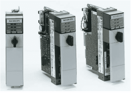
The central processing unit (CPU) is built into single-unit fixed PLCs while modular rack types typically use a plug-in module. CPU, controller, and processor are all terms used by different manufacturers to denote the same module that performs basically the same functions. Processors vary in processing speed and memory options. A processor module can be divided into two sections: the CPU section and the memory section. The CPU section executes the program and makes the decisions needed by the PLC to operate and communicate with other modules. The memory section electronically stores the PLC program along with other retrievable digital information.
The CPU executes the operating system, manages memory, monitors inputs, evaluates the user logic (ladder program), and turns on the appropriate outputs.
The CPU controls all PLC activity and is designed so that the user can enter the desired program in relay ladder logic. The PLC program is executed as part of a repetitive process referred to as a scan. A typical PLC scan starts with the CPU reading the status of inputs.
Then, the application program is executed. Once the program execution is completed, the CPU performs internal diagnostic and communication tasks. Next, the status of all outputs is updated. This process is repeated continuously as long as the PLC is in the run mode.
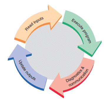
Typical PLC scan cycle
The CPU of a PLC system may contain more than one processor. One advantage of using multiprocessing is that the overall operating speed is improved. Each processor has its own memory and programs, which operate simultaneously and independently. In such configurations the scan of each processor is parallel and independent thus reducing the total response time. Fault-tolerant PLC systems support dual processors for critical processes. These systems allow the user to configure the system with redundant (two) processors, which allows transfer of control to the second processor in the event of a processor fault.
Associated with the processor unit will be a number of status LED indicators to provide system diagnostic information to the operator.
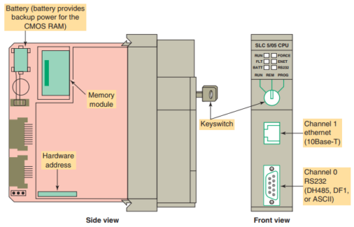
Also, a keyswitch may be provided that allows you to select one of the following three modes of operation: RUN, PROG, and REM.
RUN Position
• Places the processor in the Run mode.
• Executes the ladder program and energizes output devices.
• Prevents you from performing online program editing in this position.
• Prevents you from using a programmer/operator interface device to change the processor mode.
PROG Position
• Places the processor in the Program mode.
• Prevents the processor from scanning or executing the ladder program, and the controller outputs are de-energized.
• Allows you to perform program entry and editing.
• Prevents you from using a programmer/operator interface device to change the processor mode
REM Position
• Places the processor in the Remote mode: either the REMote Run, REMote Program, or REMote Test mode.
• Allows you to change the processor mode from a programmer/operator interface device.
• Allows you to perform online program editing.
Programming device
A programming terminal device is needed to enter, modify, and troubleshoot the PLC program. PLC manufacturers use various types of programming devices. The simplest type is the hand-held type programmer shown:
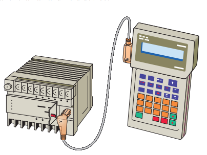
This proprietary programming device has a connecting cable so that it can be plugged into a PLC’s programming port. Certain controllers use a plug-in panel rather than a hand-held device.
Hand-held programmers are compact, inexpensive, and easy to use.
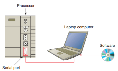
A personal computer (PC) is the most commonly used programming device. Most brands of PLCs have software available so that a PC can be used as the programming device. This software allows users to create, edit, document, store, and troubleshoot ladder logic programs. The computer monitor is able to display more logic on the screen than can hand-held types, thus simplifying the interpretation of the program. The personal computer communicates with the PLC processor via a serial or parallel data communications link or Ethernet.
A program is a user-developed series of instructions that directs the PLC to execute actions. A programming language provides rules for combining the instructions so that they produce the desired actions. Relay ladder logic (RLL) is the standard programming language used with PLCs. Its origin is based on electromechanical relay control. The relay ladder logic program graphically represents rungs of contacts, coils, and special instruction blocks.
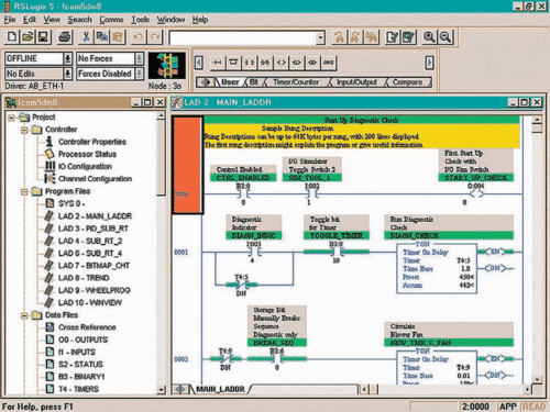
Typical PC software used to create a ladder logic program